Roof tanks are widely used in the oil, gas and petrochemical industries to store large volumes of flammable liquids such as crude oil, petrol and solvents. A fixed roof tank has a permanent roof attached to the tank shell, with a vapour space above the liquid. This vapour space can contain an explosive mixture, which increases the risk of ignition. A floating roof tank has a roof that sits directly on the surface of the liquid and rises or falls with the level, which reduces vapour build-up but introduces other risks at the rim seal where leaks and friction can occur.
Fire protection is critical for both designs because any ignition can lead to rapid flame spread, intense heat release and major asset loss. Roof fires can quickly escalate into full surface tank fires, threaten adjacent tanks through radiant heat, and result in long shutdowns and environmental damage. Effective detection and suppression systems are therefore essential to provide early warning, fast intervention and protection of people, infrastructure and stored products.
Risks
Fires in roof tanks can develop quickly and are difficult to control due to the large surface areas and the flammable nature of the stored liquids. Both fixed and floating roof tanks present specific hazards that make early detection and fast suppression essential.
- Rim seal ignition
- In floating roof tanks, vapours can escape at the rim seal. Friction, static discharge or hot work nearby can ignite these vapours, leading to a fast-spreading seal fire that can escalate to a full surface fire.
- Vapour space explosions
- Fixed roof tanks contain a vapour space above the liquid. If flammable vapours mix with air and find an ignition source, an internal explosion can occur, potentially damaging the roof and allowing fire to spread across the product surface.
- Lightning strikes
- Tanks are exposed structures and are vulnerable to lightning. A direct strike can ignite vapours or contents at the roof or seal area, often causing sudden and severe fires.
- Product leaks and spills
- Corrosion, mechanical failure or overfilling can release flammable liquid. Spilled product can form pools or vapour clouds that ignite easily and spread fire around the tank base and to nearby equipment.
- Escalation to adjacent tanks
- Radiant heat from a tank fire can heat neighbouring tanks, weaken steel structures and cause further ignitions. This can lead to a domino effect with multiple tanks involved, greatly increasing the scale and impact of the incident.
Challenges
Designing a reliable fire detection system for floating and fixed roof tanks is complex due to the environment, the scale of the risks and the need for very fast response. The following challenges must be addressed to achieve dependable early warning.
- Tank roofs and bunds cover wide surfaces. Standard point detectors may not provide sufficient coverage or response time, so systems must detect fire quickly across long distances.
- Harsh environmental conditions
- Outdoor installations face wind, rain, heat, cold and dust. These factors can affect detector sensitivity and stability, leading to false alarms or delayed detection if not properly managed.
- High levels of background interference
- Sunlight, reflections from metal surfaces, steam and process emissions can interfere with optical detection. The system must distinguish real flame and heat signatures from normal site conditions.
- Limited access for maintenance
- Tank roofs and rim seal areas can be difficult and hazardous to reach. Detection equipment must be reliable, require minimal maintenance and allow safe testing without frequent shutdowns.
- Fast fire development
- Rim seal and vapour space fires can grow rapidly. Detection must operate within seconds to allow early intervention before the fire spreads across the product surface or escalates to nearby tanks.
FyreLine EN54 Fixed
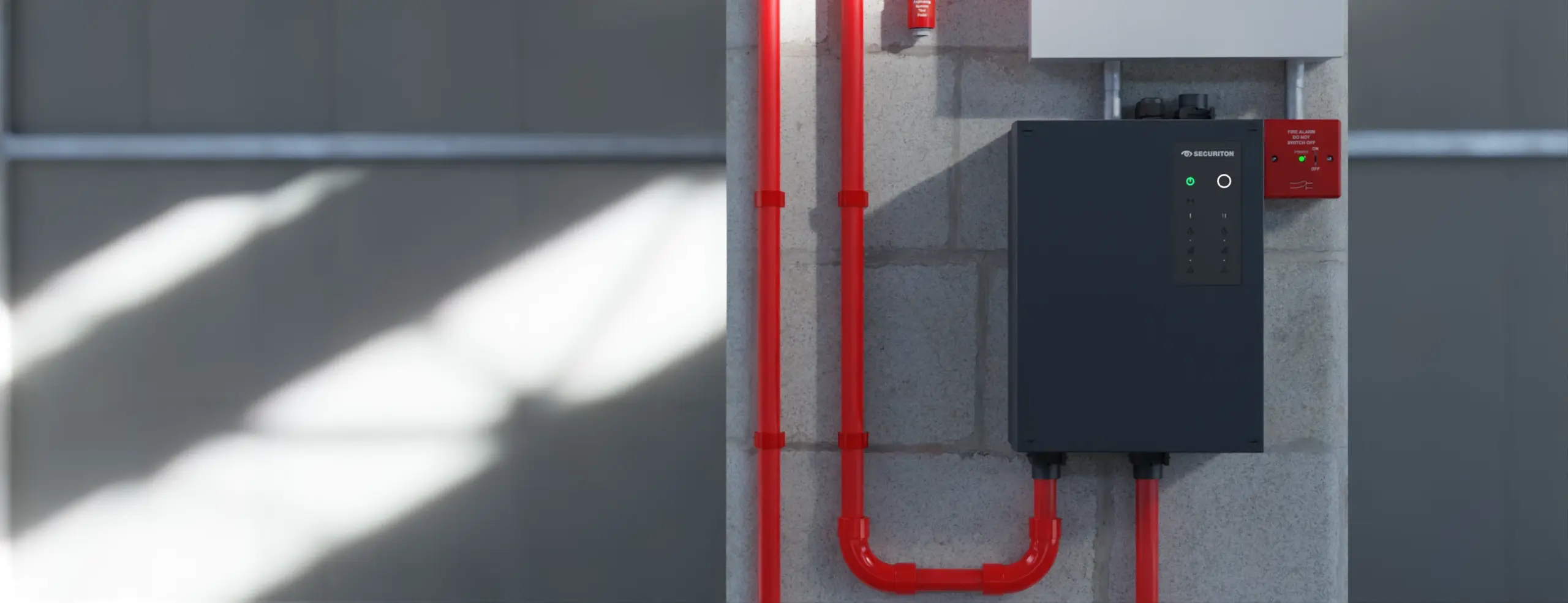
The FyreLine EN54 Fixed range is a linear heat detection system designed for early fire detection in high-risk industrial environments such as storage tanks, bunds and process areas.
It uses a heat-sensing cable installed along the risk zone, which responds to rapid temperature rise or a fixed alarm temperature. The cable is monitored by an EN54-28 approved controller that continuously checks for overheat conditions and cable faults.
When an alarm occurs, the system identifies the distance to the activated point, allowing fast location of the fire source. The range also includes end of line and test units to enable safe commissioning and routine testing. Together, these components provide a robust and compliant solution for long-distance, outdoor and hazardous applications.
Approvals
The FyreLine EN54 Fixed system is approved to BS EN54-28 for line type heat detectors, confirming its performance, reliability and suitability for use on life safety fire detection systems. The controller and sensing cable are tested for accuracy, fault monitoring and environmental durability, ensuring compliance with European fire standards. These approvals allow the system to be integrated with conventional and addressable fire alarm control panels in regulated industrial and petrochemical installations.
Independent Mode
In independent mode, each zone operates separately. If a heat-sensing cable on one zone experiences an overheat or fault condition, only that zone’s alarm or fault output is triggered. Each set of outputs connects to the fire alarm control panel or external system independently, and the two zones can use either identical or different cable temperature ratings. This mode provides straightforward monitoring for separate areas or circuits.

Interlock Mode
In interlock mode, also known as coincidence detection, both zones must register an overheat event before the alarm output is activated. This means you run two heat-sensing cables of the same rated temperature in parallel or across the same area, and the system only signals a confirmed fire condition when both cables trigger. This reduces false alarms caused by non-fire related cable activation.
Design Considerations
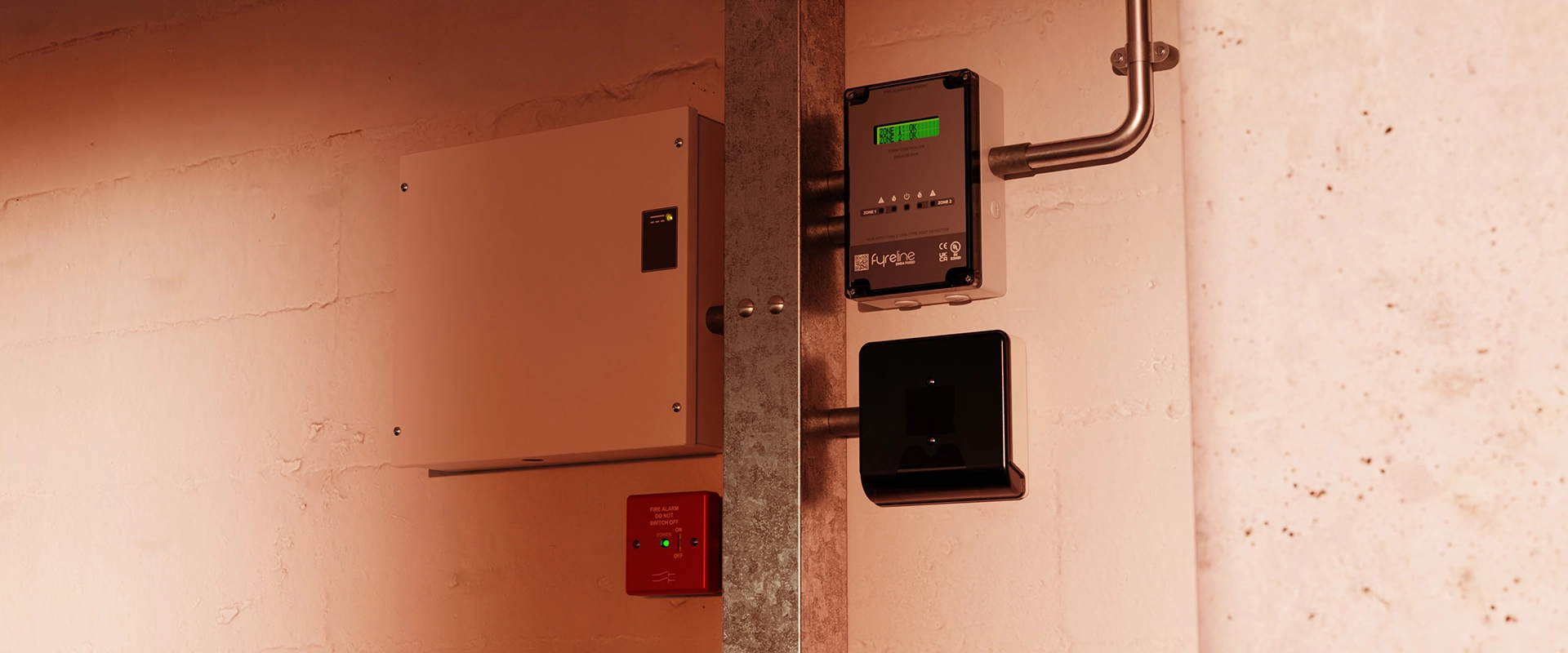
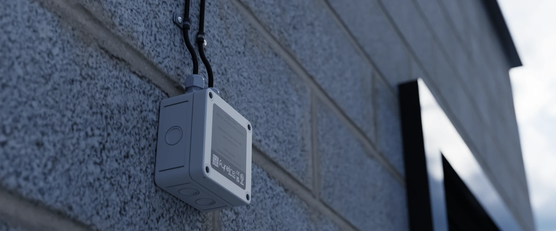
EN54 Fixed Controller Placement
For optimal performance, the FyreLine EN54 Fixed Controller should be installed in a clean, dry and easily accessible location such as a control room or local equipment shelter. It should be positioned close enough to the protected tanks to keep cable runs within the approved length limits while remaining outside high heat and hazardous zones. This allows reliable operation, clear indication of alarms and faults and safe access for routine testing and maintenance.

LHD Cable Placement
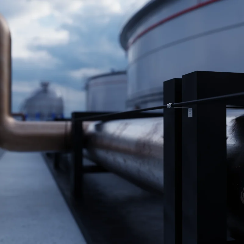
For best results, the linear heat detection cable should be installed directly in the areas where heat is most likely to develop first. On floating roof tanks this is typically around the rim seal and penetration points, while on fixed roof tanks it is placed around the roof perimeter, vents and vapour space zones. The cable should follow the risk profile closely, be securely fixed at the correct height and spacing and protected from mechanical damage. Routing should avoid sharp bends and allow for thermal expansion. Correct positioning ensures the cable is exposed to rising temperature quickly, giving fast and reliable detection before a small ignition can develop into a full surface fire.
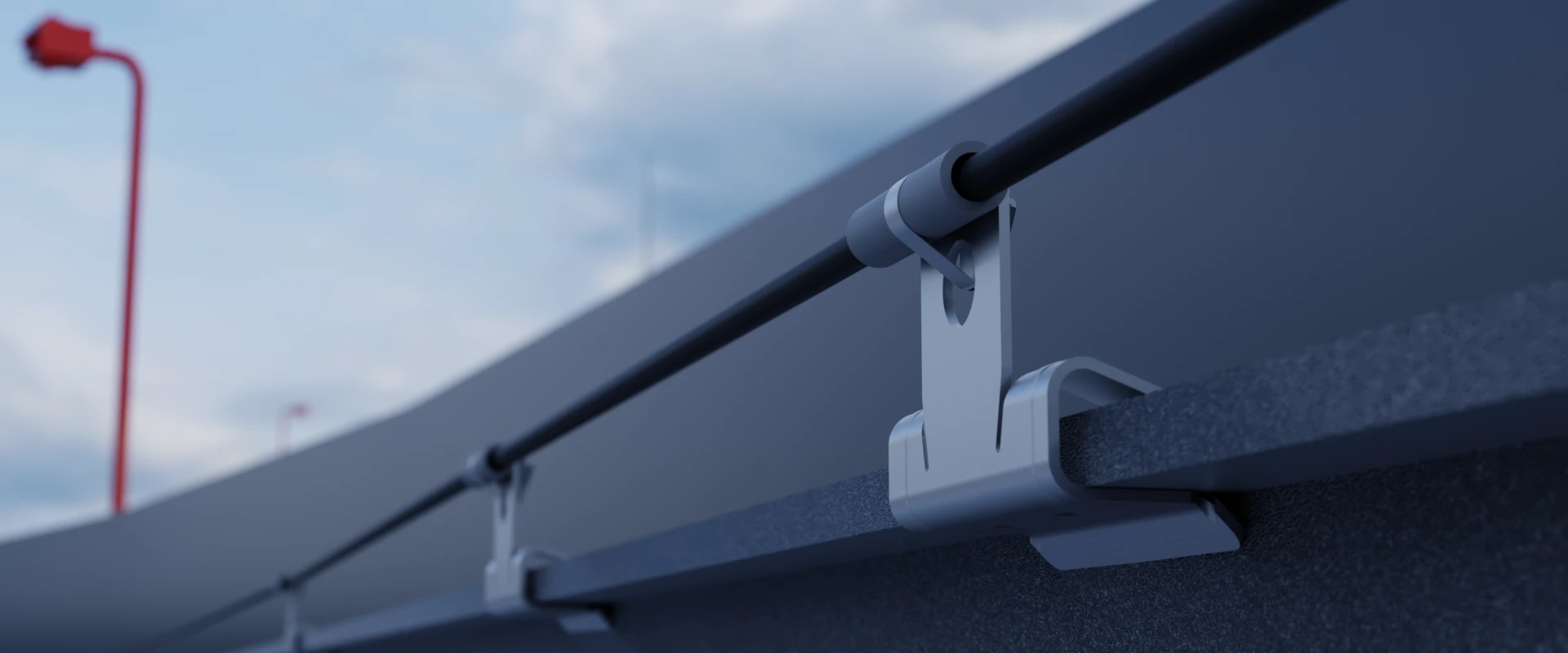
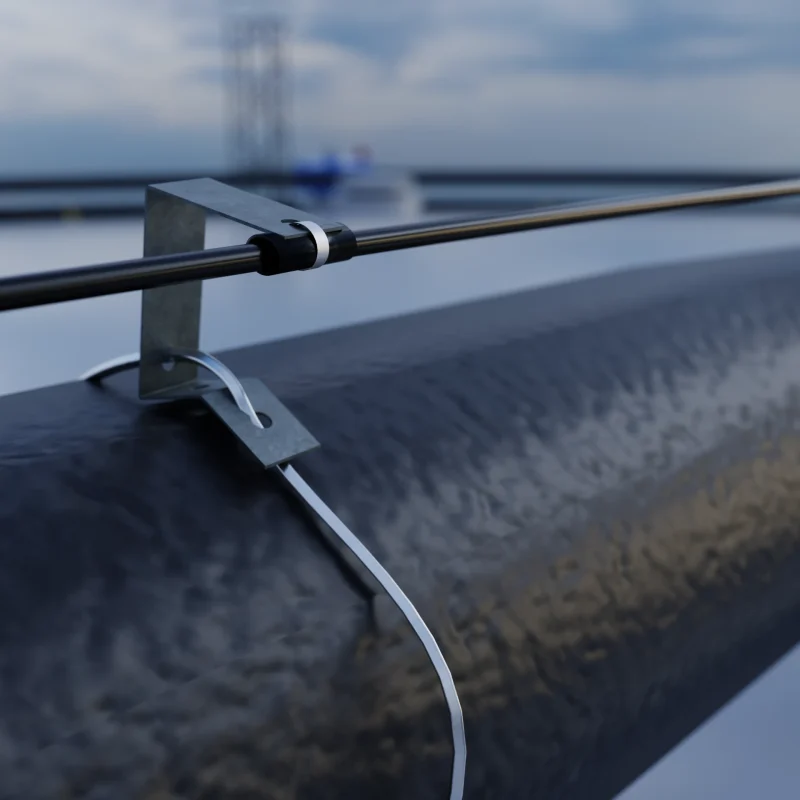
Mounting Clips

P-Clips provide a secure and cushioned mounting point for FyreLine Resettable LHD cables. They are best placed at regular intervals along the cable route. Their flexible grip helps prevent cable damage while maintaining firm support.

J-Clips are used to securely fix FyreLine Resettable LHD cables in place. They should be installed at regular intervals along the cable route to maintain proper positioning and tension. Placement should avoid contact with sharp edges.
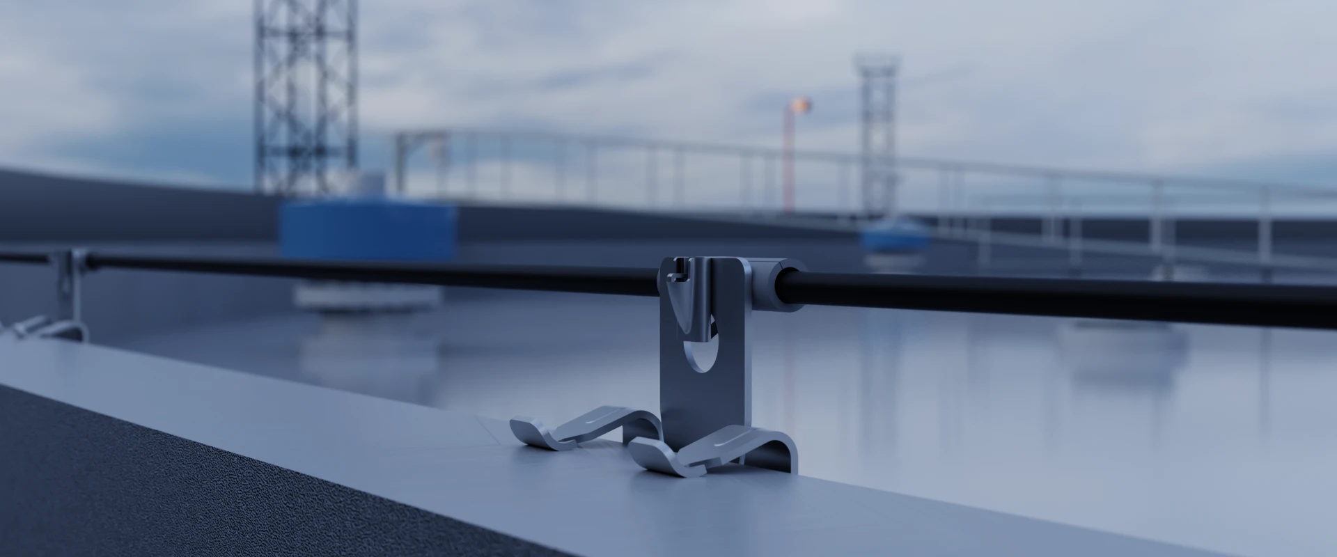
The girder clip provides secure, non-invasive fixing of the LHD cable to steel beams, ensuring correct spacing and reliable positioning without drilling or welding.
EOL Placement
The end of line module provides correct electrical termination and continuous fault monitoring of each LHD cable zone. It should be installed in a weatherproof, accessible location at the furthest point of the cable run to allow reliable supervision and safe testing.

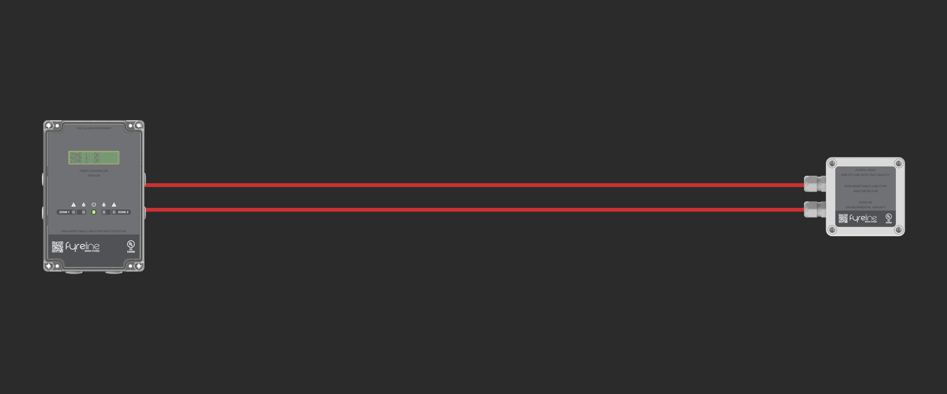
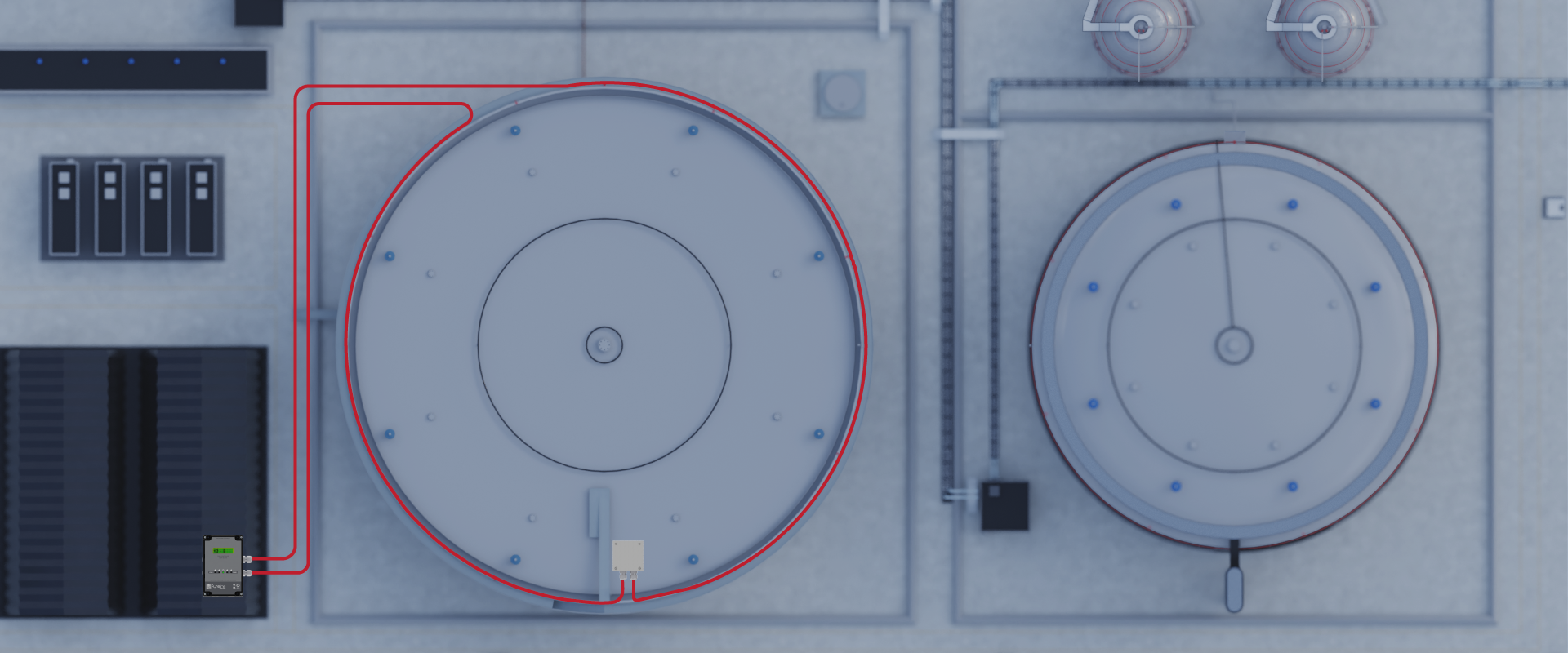
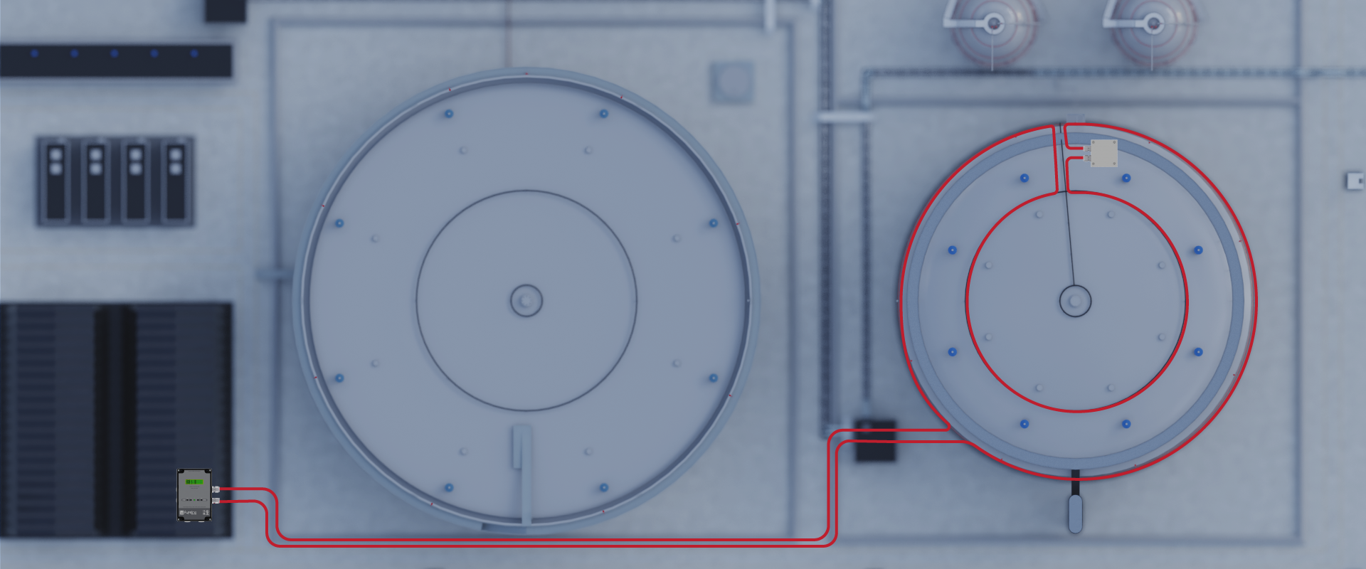
Typical Wiring Diagram
A typical wiring arrangement connects each length of linear heat detection cable from the protected tank area back to the FyreLine EN54 Fixed controller in a radial configuration.
The cable is terminated at the end of the run with an end of line module to allow continuous monitoring for open or short circuit faults. Fire-rated cable should be used throughout, with segregation from power circuits and suitable mechanical protection where the cable enters buildings or control panels. The controller outputs are then wired to the site fire alarm system or suppression interface to provide alarm, fault and status signals for coordinated response.
For ATEX classified areas such as tank farms, the FyreLine EN54 Fixed Controller and any associated control equipment must always be installed in a designated safe zone outside the hazardous area to prevent ignition risk and ensure compliance with explosion protection requirements.
Why Choose Eurofyre?
- Complete System Supplier
- Eurofyre supplies all aspects of fire detection including linear heat detection and its associated products and can provide expert advice and consultation.
- Demonstration and Training
- We offer demonstrations and expert training on a range of systems, including FyreLine linear heat detection systems, in our very own sophisticated training facility.
- After-Sales Support
- Eurofyre offers both on-site and telephone support to assist you in ensuring that your system is fully functional and operating at maximum efficiency. Our after-sales care and support are second to none.
For more information about EN54 Fixed Linear Heat Detection, or to discuss any of the other products that Eurofyre has to offer, please feel free to get in touch either by phone on +44 (0) 1329 835 024, by email to sales@eurofyre.co.uk or via the online enquiry form situated on our contact page.
Don’t forget you can follow us on LinkedIn, Twitter and Facebook or sign up to our newsletter (in the footer below) to receive all the latest information from Eurofyre.